Test a Route
Network operators can configure and test a route to make sure the call routing rule, the manipulation rule, the topology status, etc., all perform per expectations, without impacting live calls traffic.
|
1.
|
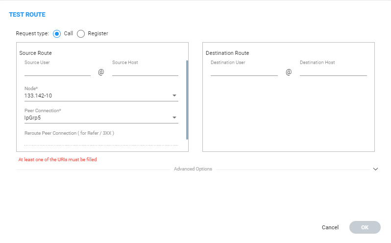
In the Network Map page, right-click the connection between a node and a VoIP Peer (Peer Connection) and then from the popup menu, click the Test Route option. |
|
2.
|
[Optional] Enter the Source and Destination Route. From the drop-down menus, select the Node, Peer Connection, Reroute Peer Connection (only for REFER/3XX). |
|
3.
|
Under 'Advanced Options', select the routing rules mode: |
|
●
|
Live. When a new call destination is calculated, the Routing Rule is taken into consideration and live traffic may be impacted. |
|
●
|
Test. Tests the Routing Rule or Dial Plan offline without impacting or disrupting live calls traffic. |
|
●
|
Live and Test selected together. The Routing Rule is considered when: |
|
◆
|
calculating the live routing path -and- |
|
◆
|
testing a route in the live topology map and in the offline planning page |
Each routing rule can be enabled or disabled separately for Live mode and / or Test mode (see also under Add a Routing Rule).
|
4.
|
Under 'Advanced Options', select the call trigger. By default, the Initial option is enabled. See step 11 under Add a Routing Rule for more information about call triggers. |
|
5.
|
Optionally, test the route with a specific ARM Router (also supported in 'Test Route' activated from ‘Offline Planning’): Under 'Advanced Options', select from the 'Router' drop-down: |
|
●
|
Any (default) = the ARM Configurator contacts any ARM Router to perform a ‘Test Route’ and get the results; the ARM Router is chosen randomly. |
|
●
|
Select a specific ARM Router for a test call. |
Use this feature for debugging and locating potential issues.
|
6.
|
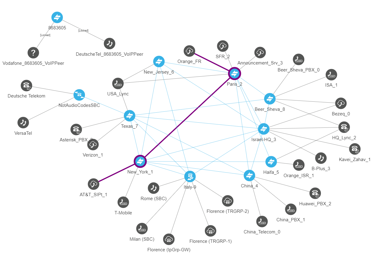
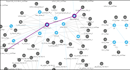
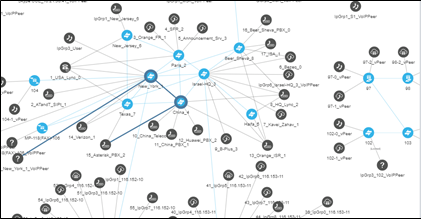
Click Find Routes. Test routing is performed as if a real call is occurring, taking Operative State and Admin State of topology entities (Connections, nodes, Peer Connections), and the Admin State of routing rules, into account. In addition, the entity's Quality or Time/Date criteria are taken into consideration if required by the Routing Rule (Advanced Condition). The Route Path is highlighted purple (shown in the following figure). |
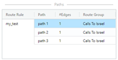
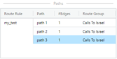
The 'Network Summary' pane on the right of the Network Map page displays detailed information under 'Paths'.
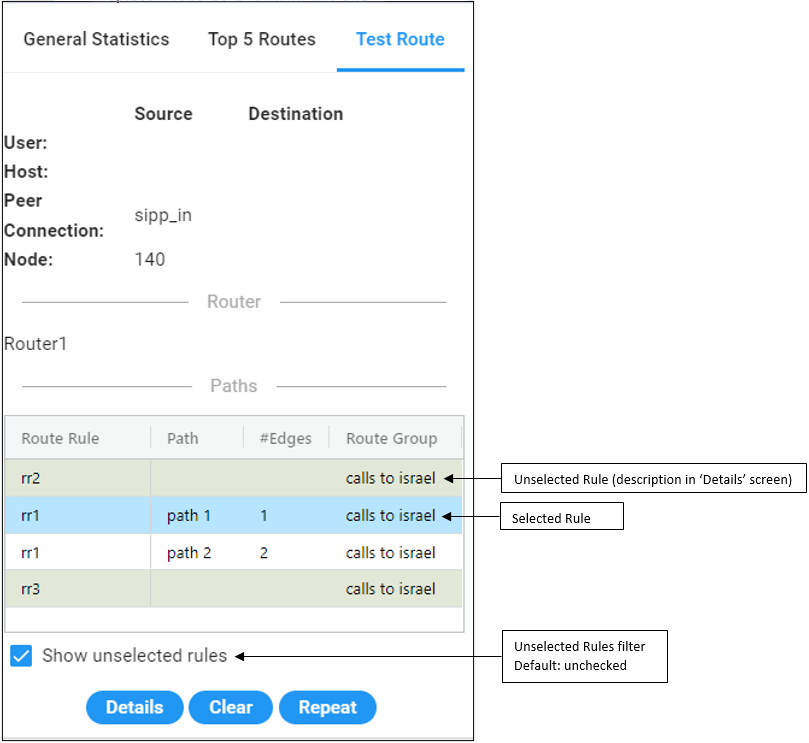
Gray = Unselected Rule
White = Selected Rule
Blue = selected row
if we have unselected rules they'll be grayed.
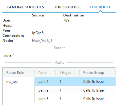
Test Route displays forking. If Test Route criteria match a Routing Rule with Forking Routing Method, it’s displayed accordingly in the 'Paths' section as shown below.
|
7.
|
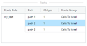
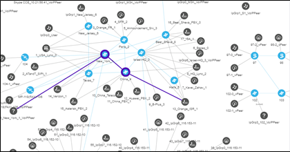
Select a path (path 1, 2 or 3 in the preceding figure); that path of the call’s forking is displayed in a unique color in the Network Map page as shown in the following three figures. Note that for each forking leg (forking path), its details are available.
|
Forking Path 1
Forking
Path 2
Forking
Path 3
If there are no paths, the Details button will nonetheless be displayed; clicking it will show the pre-route Manipulations and pre-route Unselected Rules (see the descriptions of the columns CHANGED BY and DESCRIPTION below for more information about Unselected Rules).
|
8.
|
In the Test Route pane, click the Details button. |
|
9.
|
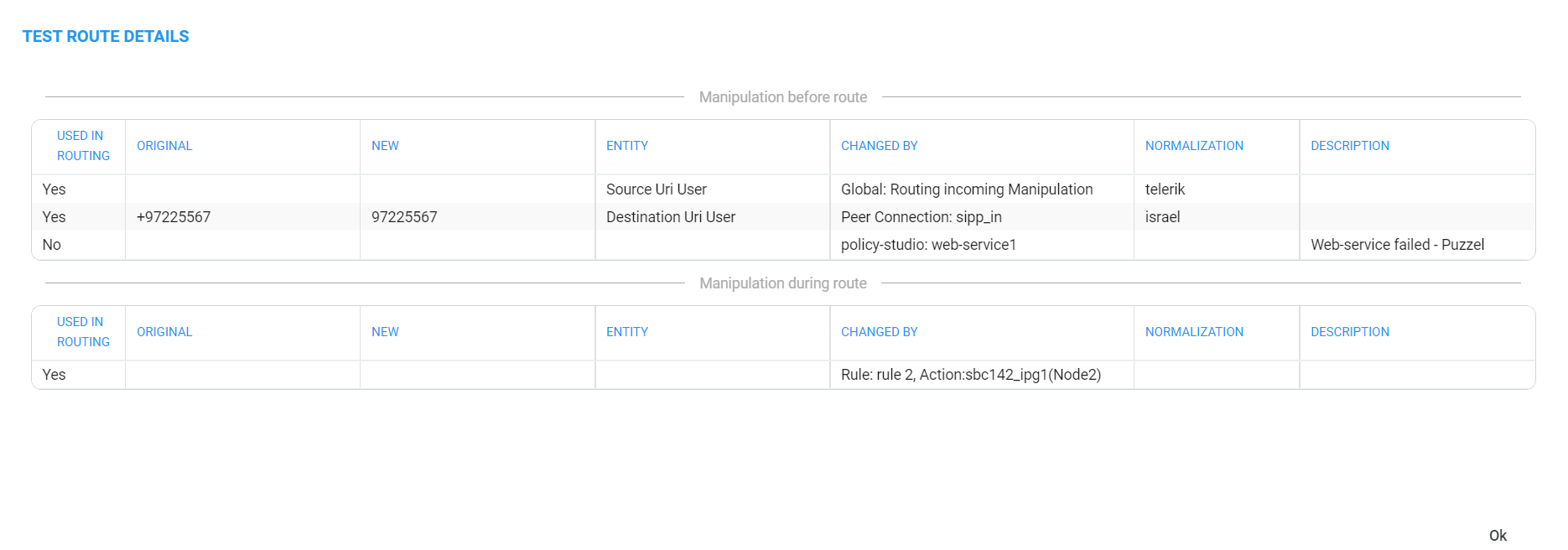
In the above example of the Test Route Details screen: |
|
●
|
Compare the column ORIGINAL to the column NEW; the number changes if a normalization rule was applied. The normalization rule is configured in the Normalization Group rules attached to the Peer Connection. For related information, see also under Peer Connections Page Actions and Examples of Normalization Rules . |
|
●
|
The screen example indicates when manipulation was performed: |
|
◆
|
Manipulation before route (upper screen section)
|
|
◆
|
Manipulation during route (lower screen section)
|
In the screen example, manipulation was performed before and during route.
|
●
|
Column ENTITY indicates which part of the SIP Request was manipulated. |
|
◆
|
Possible values: Source URI User, Source URI Host, Destination URI User, Destination URI Host, Destination IP Address, Destination Port, Destination Protocol, User Credential User Name, User Credential Password |
|
●
|
The column CHANGED BY (use the previous figure as reference): |
|
◆
|
the 'No' in the third row under the column USED IN ROUTING indicates an unselected Policy Studio that was not applied (see step 8 under Web-based Services) |
|
◆
|
also under 'Manipulation during route', the Yes/No in the first row under the column USED IN ROUTING indicates the selected/unselected Test Route path. |
|
●
|
The column NORMALIZATION indicates which 'Manipulation Group' the entity passed through, according to which regular expression the entity was changed. |
|
●
|
A new Routing Rule is by default added in ‘Test Mode’ (not 'Live'). To test the rule before switching it to live, use the ‘Test’ option of ‘Test Route’.
|
|
●
|
After performing Test Route, the results (including the selected path) are preserved in the Network Map even if you switch to another tab.
This is convenient when debugging a Dial Plan, after fixing a Routing Rule and reverting to testing it in the Network Map with the ‘Test Route’ feature. |